Hydraulic Propulsion, Cavitation Dominance, and Operating at the Edge of Stability
ENGINE ROOM → Propulsion & Transmission
System Group: High-Speed & Specialised Propulsion
Primary Role: High-speed thrust generation through internal hydraulic acceleration
Interfaces: Prime Movers · Gearboxes · Intake Ducts · Hull Structure · Control Systems · Steering & Manoeuvring
Operational Criticality: Continuous within a narrow operating envelope
Failure Consequence: Thrust collapse → violent vibration → loss of control → structural and machinery damage
Waterjets are not alternative propellers.
They are hydraulic machines operating continuously in a cavitation-dominated regime where efficiency, stability, and survivability are tightly coupled.
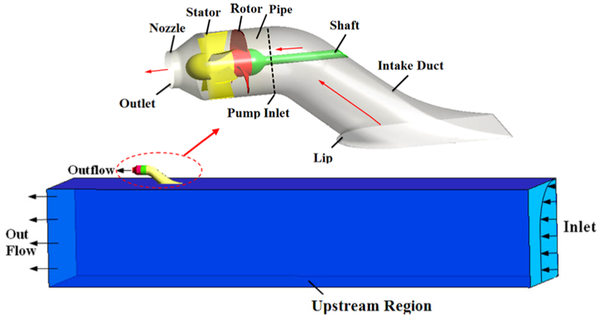
Position in the Plant
Waterjet propulsion replaces the external propeller with an internalised flow system that accelerates seawater through a duct, converting shaft power into jet momentum. The propulsion unit becomes part of the hull structure rather than an appendage attached to it.
This integration fundamentally alters the propulsion problem:
- hydrodynamic losses dominate over mechanical losses
- inflow quality becomes as critical as shaft power
- propulsion efficiency depends more on hull–intake interaction than blade geometry alone
From an engineering standpoint, waterjets move the primary risk from exposed rotating machinery to flow integrity, cavitation control, and structural fatigue at the intake boundary.
Contents
System Purpose and Design Intent
Hydraulic Operating Principles and Energy Conversion
Intake Geometry, Boundary Layers, and Inflow Reality
Cavitation, Ventilation, and Erosion Mechanisms
Mechanical Components and Internal Load Paths
Control, Reversal, and Steering Architecture
Thermal Behaviour and Continuous Operation Limits
Failure Development and Damage Progression
Human Oversight and Engineering Judgement
1. System Purpose and Design Intent
The design intent of waterjet propulsion is high-speed efficiency with minimal appendage drag.
Waterjets are selected when vessels require:
- high service speed
- rapid acceleration
- shallow draft
- reduced exposure to debris or grounding
They achieve this by eliminating exposed propellers, shaftlines, and rudders. However, this advantage exists only when the vessel operates within a narrow hydrodynamic envelope.
Waterjets are not tolerant of off-design operation. Unlike propellers, which degrade gradually, waterjet efficiency collapses abruptly when inflow quality deteriorates.
2. Hydraulic Operating Principles and Energy Conversion
Waterjets function as axial-flow hydraulic machines.
The impeller increases the kinetic energy of the water. The stator straightens rotational flow, converting swirl into axial momentum. The nozzle then converts velocity into thrust.
Energy losses occur at every stage:
- intake losses from boundary layer ingestion
- impeller losses from cavitation and blade loading
- stator losses from flow separation
- nozzle losses from non-ideal expansion
Unlike propellers, where thrust scales relatively smoothly with RPM, waterjet thrust is highly sensitive to inlet pressure and flow uniformity. Small disturbances upstream cause disproportionate loss of thrust.
3. Intake Geometry, Boundary Layers, and Inflow Reality
The intake is the most critical component of the entire system.
Waterjet intakes operate within the hull boundary layer, where:
- velocity is reduced
- turbulence is high
- air entrainment is possible
- debris concentration increases
Poor intake geometry leads to:
- uneven impeller loading
- asymmetric thrust
- vibration transmitted into the hull
At low speed, intake flow is marginal. At high speed, pressure recovery becomes critical. The intake must function across this entire range — a requirement that is fundamentally conflicting.
Intake damage, fouling, or deformation immediately degrades propulsion performance, often without visible external signs.
4. Cavitation, Ventilation, and Erosion Mechanisms
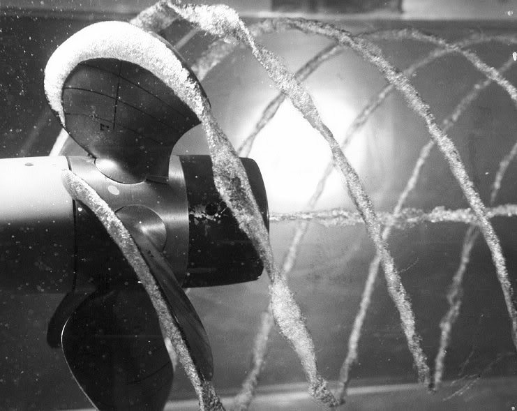
Cavitation is not an abnormal condition in waterjets.
It is the dominant operating regime under which they are designed to function.
Cavitation is the formation and subsequent collapse of vapour-filled voids within a liquid when local pressure falls below the vapour pressure of the fluid. In seawater propulsion systems, this condition is reached not through elevated temperature, but through pressure reduction induced by velocity and blade geometry.
Waterjet impellers operate at high rotational speed with significant angles of attack. As water accelerates over the suction side of the impeller blades, local static pressure drops sharply. When this pressure falls below the vapour pressure of seawater at ambient temperature, the water undergoes phase change and vapour cavities form.
These vapour cavities are not stable features. They are transient structures that grow as pressure continues to drop and then collapse violently when transported into regions of higher pressure downstream.
The collapse mechanism is the destructive element.
When local pressure exceeds vapour pressure, condensation begins at the cavity boundary. The vapour bubble contracts asymmetrically, collapsing inward at its weakest point. This collapse drives a high-velocity microjet of liquid toward nearby solid surfaces. Localised pressure spikes generated during this implosion can reach hundreds of megapascals, orders of magnitude higher than average operating pressures within the propulsion system.
When this process occurs adjacent to solid boundaries — such as impeller blades, stator vanes, or intake surfaces — the resulting microjets and pressure waves impose repeated, concentrated impact loads on the material surface. Over time, this produces characteristic crater-shaped erosion, surface embrittlement, and material removal.
In waterjets, cavitation is continuous rather than intermittent. Unlike propellers, where cavitation may be confined to specific operating points, waterjet impellers operate permanently near vapour pressure limits due to intake losses, high flow velocity, and constrained duct geometry.
Ventilation compounds this behaviour.
Ventilation occurs when air is ingested into the waterjet intake, either from the free surface, hull vortices, or disturbed inflow during manoeuvring. Unlike cavitation, ventilation introduces compressible gas into the flow. This destabilises pressure recovery, collapses thrust abruptly, and induces violent vibration as the impeller alternates between liquid and gas loading.
Cavitation and ventilation together produce a highly unstable hydraulic environment. Thrust fluctuations are transmitted directly into bearings, shafts, and the hull structure, while electrical and mechanical systems experience rapid load oscillation.
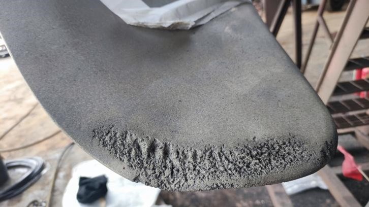
Material damage manifests in predictable forms.
Early-stage cavitation erosion presents as fine pitting on blade suction surfaces and leading edges. As erosion progresses, surface roughness increases, promoting boundary layer separation and intensifying cavitation activity. Stator vanes experience leading-edge thinning and profile distortion, reducing flow straightening effectiveness and further degrading efficiency.
Once surface finish is lost, hydraulic losses increase disproportionately. Unlike propellers, where polishing can restore some efficiency, waterjet components operate inside confined ducts where surface damage fundamentally alters flow behaviour. Minor repairs rarely recover original performance.
Importantly, cavitation damage does not immediately present as overheating or alarm conditions. Instead, it erodes margin. The system continues to function, but with progressively reduced tolerance to load changes, manoeuvring demands, and environmental disturbances.
From an operational standpoint, cavitation in waterjets must be understood not as something to be “eliminated”, but as something to be managed and constrained.
Attempts to operate waterjets outside their intended envelope — prolonged low-speed operation, aggressive manoeuvring, excessive reversal at high RPM, or degraded intake conditions — accelerate cavitation damage exponentially. The transition from acceptable erosion to catastrophic performance loss can be rapid and irreversible.
Unlike conventional propellers, waterjets do not fail gradually. Once cavitation-induced degradation reaches a critical threshold, thrust collapse, violent vibration, and loss of control authority can occur with little warning.
Judgement lies in recognising when cavitation has shifted from a tolerable operating condition to a destructive one — long before physical failure becomes unavoidable.
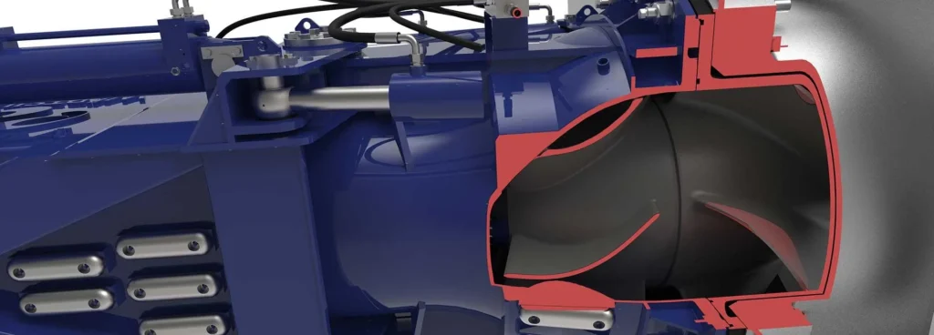
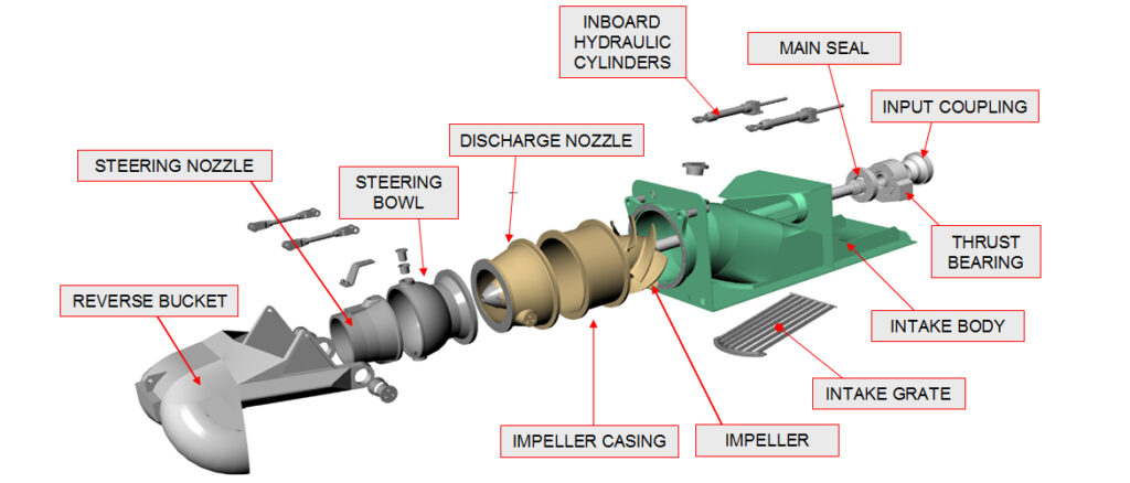
5. Mechanical Components and Internal Load Paths
Although waterjets appear mechanically simple, internal loads are severe.
Major components include:
- impeller and shaft
- thrust bearing
- stator vanes
- steering and reversing buckets
- actuators and linkages
Thrust loads are absorbed internally and transmitted directly into the hull structure. Load reversals during manoeuvring impose shock forces on bearings and actuators.
Because the unit is rigidly integrated into the hull, vibration and fatigue propagate structurally rather than dissipating through shaftlines.
6. Control, Reversal, and Steering Architecture
Waterjet control relies on flow deflection, not thrust reversal.
Steering and reversing buckets redirect the jet stream to generate lateral or reverse thrust. These systems must respond rapidly and symmetrically.
Failure modes include:
- delayed bucket response
- asymmetric deflection
- hydraulic leakage or actuator drift
Improper coordination between engine RPM and bucket position causes load spikes, vibration, and loss of control authority.
Reversal at high RPM is structurally aggressive and should be minimised in normal operation.
7. Thermal Behaviour and Continuous Operation Limits
Waterjets are thermally constrained machines.
Bearing lubrication, seal cooling, and actuator hydraulics rely on limited internal cooling. At low speed, available cooling flow is poor. At high speed, cavitation heating increases.
Repeated short operations are particularly damaging. Heat accumulates internally without sufficient dissipation, leading to:
- lubricant breakdown
- seal hardening
- bearing distress
A waterjet that remains within temperature limits during one manoeuvre may exceed limits cumulatively over repeated cycles.
8. Failure Development and Damage Progression
Waterjet failures rarely occur without warning, but the warning signs are subtle:
- increased vibration during acceleration
- delayed thrust response
- rising noise levels
- declining top speed
Failure progression typically follows:
- intake or impeller erosion
- cavitation intensification
- bearing and seal degradation
- hydraulic instability
- sudden thrust collapse
By the time thrust loss becomes obvious, structural damage is often already extensive.
9. Human Oversight and Engineering Judgement
Waterjets demand discipline.
Engineers protect them by:
- respecting operating speed envelopes
- avoiding prolonged low-speed operation
- coordinating manoeuvring with the bridge
- monitoring vibration character, not just magnitude
A waterjet that “still achieves speed” may already be operating beyond recoverable efficiency.
Judgement, not automation, prevents escalation.
Relationship to Adjacent Systems and Cascading Effects
Waterjet performance directly influences:
- engine loading and combustion stability
- gearbox torque transients
- hull vibration and fatigue
- manoeuvring safety at speed
Because waterjets fail abruptly, their integration with propulsion control and operational procedures is critical to vessel safety.