Load Transmission, Alignment Reality, and the Quiet Progression of Failure
ENGINE ROOM → Propulsion & Transmission
System Group: Shaftline & Power Transmission
Primary Role: Transmission of torque and thrust from prime mover to propeller
Interfaces: Main Engine · Gearbox · Thrust Bearing · Stern Tube · Propeller · Hull Structure
Operational Criticality: Continuous
Failure Consequence: Progressive wear → vibration → seal failure → bearing damage → loss of propulsion
Shafting systems do not fail loudly.
They fail slowly, elastically, and invisibly — until alignment is lost, oil is contaminated, or propulsion integrity is compromised.
Position in the Plant
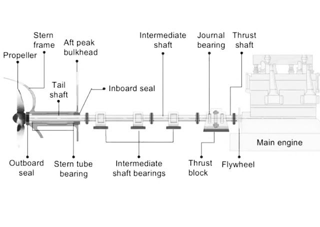
The shaftline is the mechanical spine of the propulsion plant. It carries torque, absorbs thrust, tolerates hull movement, and transmits hydrodynamic disturbances from the propeller deep into the machinery space.
Unlike engines or gearboxes, shafting has no active control. Its behaviour is dictated entirely by geometry, alignment, lubrication, and load history. Once installed, the system operates continuously for decades, accumulating fatigue, wear, and distortion from every operating condition encountered.
Shafting problems are rarely isolated. They are systemic, cumulative, and strongly influenced by decisions made far upstream — in propeller loading, manoeuvring practice, and maintenance philosophy.
Contents
Shaftline Purpose and Design Intent
Shaft Geometry, Materials, and Load Paths
Thrust Transmission and Bearing Hierarchy
Shaft Bearings: Types, Lubrication, and Behaviour
Stern Tube Bearings: Oil vs Water Lubrication
Shaft Seals and Environmental Boundaries
Alignment Philosophy and Hull Interaction
Failure Development and Damage Progression
Human Oversight and Engineering Judgement
1. Shaftline Purpose and Design Intent
The shaftline exists to transmit power while remaining dimensionally stable under changing load, temperature, and hull geometry.
Design intent is not rigidity.
It is controlled flexibility.
Shafts must tolerate:
- torsional fluctuation from combustion
- axial thrust from the propeller
- bending from hull deflection
- misalignment introduced during operation
Perfect alignment exists only during installation, under static conditions. Once the vessel is afloat, loaded, and operating, alignment becomes dynamic. The shaftline must survive this reality without concentrating stress beyond material limits.
2. Shaft Geometry, Materials, and Load Paths
Propulsion shafts are typically forged steel components designed to operate well below ultimate strength but close to fatigue limits over long service lives.
Key load components include:
- torsional shear from torque
- axial compression from thrust
- bending from misalignment and hull deflection
Stress concentrations occur at:
- fillets
- keyways
- coupling faces
- propeller tapers
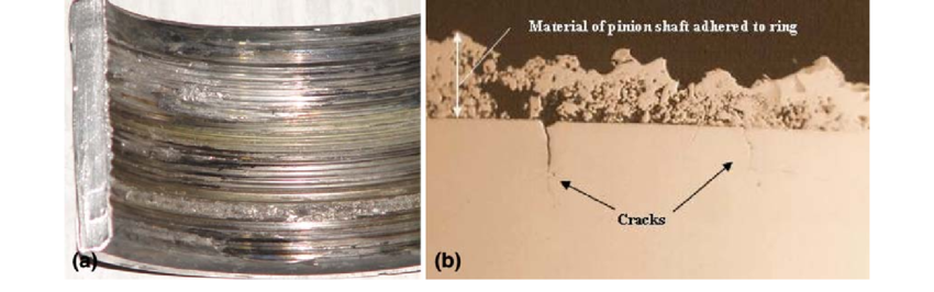
Fatigue does not announce itself. It accumulates cycle by cycle. Small surface defects, corrosion pits, or fretting scars can become crack initiation sites long before vibration levels become alarming.
3. Thrust Transmission and Bearing Hierarchy
Thrust generated at the propeller must be absorbed and transferred into the hull structure. This function is assigned to the thrust bearing, either integrated into the main engine, gearbox, or as a separate unit.
The hierarchy is deliberate:
- journal bearings support radial load
- thrust bearings absorb axial load
- stern tube bearings stabilise the shaft at the hull interface
If thrust is not properly absorbed where intended, it migrates. Bearings not designed for axial load begin to fail in ways that appear unrelated to propulsion.
A thrust bearing operating at its limit rarely fails catastrophically. It transfers distress downstream.
4. Shaft Bearings: Types, Lubrication, and Behaviour
Shaft bearings operate under mixed lubrication regimes. Full hydrodynamic films exist only under ideal conditions.
Common bearing types include:
- white metal journal bearings
- tilting pad bearings
- composite bearings in water-lubricated systems
Bearing health depends on:
- oil or water film integrity
- correct alignment
- stable loading
Temperature rise is a late indicator.
Loss of oil film begins much earlier, often masked by transient operating conditions.
Localised wiping, edge loading, or micro-fatigue may progress for months before alarms activate.
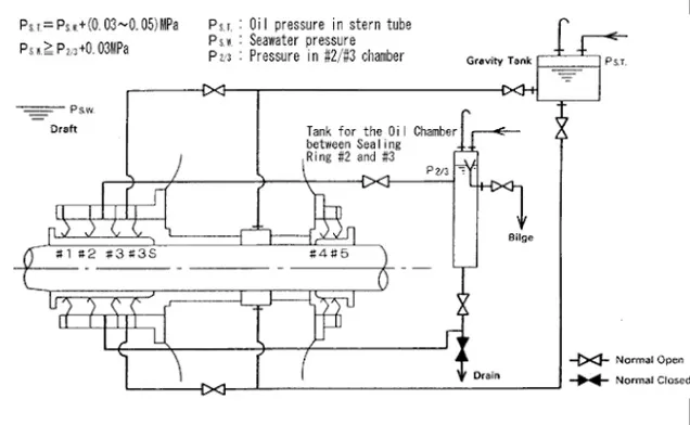
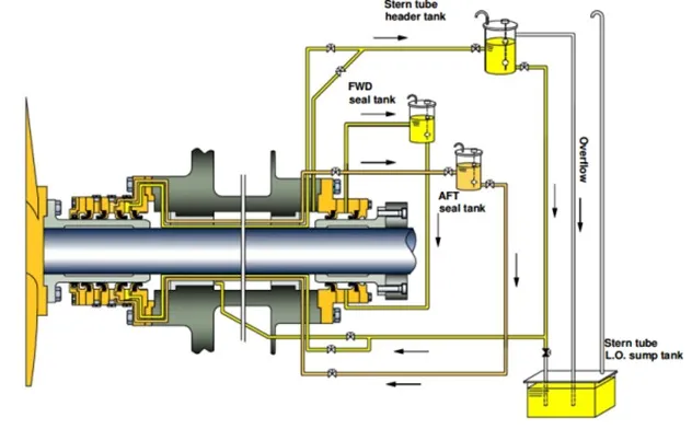
5. Stern Tube Bearings: Oil vs Water Lubrication
Oil-Lubricated Stern Tubes
Oil-lubricated systems provide controlled chemistry and predictable lubrication. They rely on:
- seal integrity
- oil cleanliness
- correct static head
Failure modes include:
- seal wear allowing seawater ingress
- oil leakage overboard
- emulsification and loss of film strength
Once seawater enters the system, corrosion begins internally. Complete oil replacement does not reverse damage already initiated.
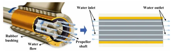
Water-Lubricated Stern Tubes
Water-lubricated systems eliminate oil pollution risk but introduce new sensitivities.
Bearing materials must tolerate:
- variable water quality
- abrasive particles
- biological fouling
Loss of lubrication flow, even briefly, can cause rapid bearing damage. Unlike oil systems, there is little thermal buffering.
6. Shaft Seals and Environmental Boundaries
Shaft seals are boundary systems. They separate rotating machinery from the sea.
They are not permanent barriers.
They are controlled leakage devices.
Seal systems accommodate:
- shaft movement
- thermal expansion
- eccentricity
- wear
Common failure paths include:
- face wear
- spring fatigue
- debris ingestion
- pressure imbalance
A seal that is “only leaking slightly” is not stable. Leakage indicates loss of control. Catastrophic failure often follows an extended period of accepted seepage.
7. Alignment Philosophy and Hull Interaction
Alignment is not a one-time event.
Hull girder deflection varies with:
- loading condition
- ballast state
- sea state
- thermal gradients
Shaft alignment must therefore tolerate change without inducing harmful bearing loads.
Misalignment manifests as:
- edge loading on bearings
- elevated vibration at specific RPM
- accelerated seal wear
Real-world alignment is a compromise between ideal geometry and operational reality. Over-tight tolerances often reduce survivability rather than improving it.
8. Failure Development and Damage Progression
Shaftline failures progress predictably:
- minor misalignment or load change
- bearing film instability
- surface distress and heat generation
- seal degradation
- contamination and accelerated wear
The system often continues to operate “normally” throughout early stages. By the time propulsion behaviour changes noticeably, options are limited.
9. Human Oversight and Engineering Judgement
No sensor measures alignment directly during operation.
Engineers infer shaft health through:
- vibration character
- oil analysis trends
- temperature distribution
- seal behaviour
A stable temperature does not guarantee a stable bearing.
A quiet shaftline does not guarantee correct alignment.
Judgement bridges the gap between instrumentation and reality.
Relationship to Adjacent Systems and Cascading Effects
Shaftline behaviour directly affects:
- propeller performance
- gearbox loading
- bearing life throughout the plant
- seal integrity and environmental compliance
- hull vibration and structural fatigue
Without understanding shafting, propulsion diagnostics become fragmented and reactive.