Distributed Propulsion, Electrical Load Reality, and the Consequences of Integration Failure
ENGINE ROOM → Propulsion & Transmission
System Group: Integrated & Electric Propulsion
Primary Role: Combined propulsion, steering, and thrust vectoring
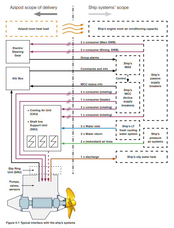
Interfaces: Electrical Generation · Power Management · Cooling Systems · Hull Structure · Control & Automation
Operational Criticality: Continuous
Failure Consequence: Loss of propulsion and steering → electrical instability → reduced redundancy → operational restriction
Pods are not propulsion add-ons.
They are structural propulsion systems that merge electrical, mechanical, and hydrodynamic domains into a single failure boundary.
Position in the Plant
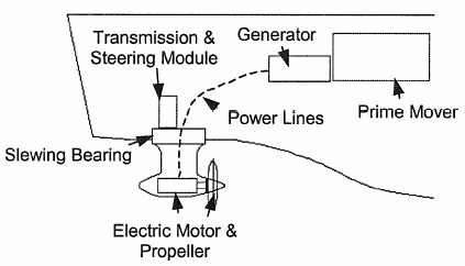
Podded propulsion systems relocate the propulsion motor outside the hull, integrating thrust generation, steering, and load absorption into a single submerged unit. Power is transmitted electrically rather than mechanically, shifting risk away from long shaftlines and toward power electronics, insulation systems, and cooling integrity.
From an engineering perspective, pods represent a redistribution of risk, not a reduction. Shaft alignment problems are replaced by cable integrity concerns. Gearbox wear is replaced by bearing and seal dependency. Mechanical simplicity is traded for electrical and control complexity.
Contents
System Purpose and Design Intent
Electric Propulsion Architecture and Power Flow
Hydrodynamic and Structural Implications
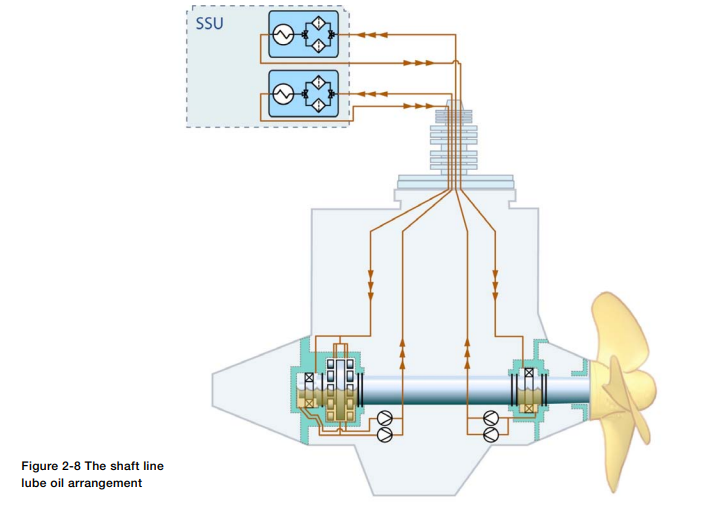
Bearings, Seals, and Submerged Machinery Reality
Cooling, Insulation, and Thermal Limits
Control, Redundancy, and Power Management
Failure Development and Damage Progression
Human Oversight and Engineering Judgement
1. System Purpose and Design Intent
The design intent of podded propulsion is integration.
By combining propulsion and steering into a single unit, designers aim to improve manoeuvrability, reduce internal machinery volume, and enable flexible power generation layouts.
However, this integration eliminates traditional separation between systems. A pod failure is simultaneously:
- a propulsion failure
- a steering failure
- an electrical load disturbance
- a structural and sealing risk
Redundancy must therefore exist at the system architecture level, not just component level.
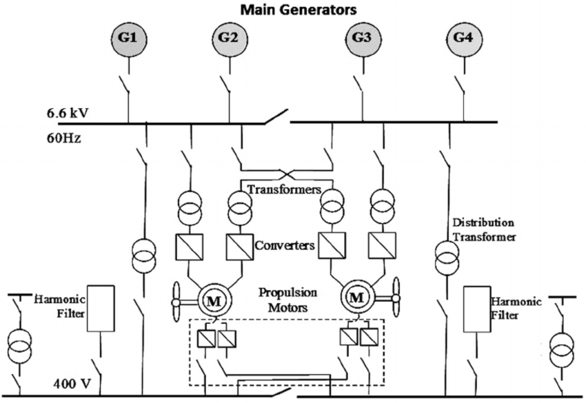
2. Electric Propulsion Architecture and Power Flow
Electric propulsion systems decouple prime movers from propulsors.
Diesel generators, gas turbines, or hybrid sources feed a common electrical bus. Power electronics convert and condition this energy for propulsion motors.
This architecture introduces:
- harmonics
- transient load spikes
- thermal stress on converters
- dependency on power management logic
A pod does not draw “smooth” power. It draws dynamically varying electrical load that reflects hydrodynamic resistance, manoeuvring commands, and environmental forces.
Electrical stability becomes a propulsion safety issue.
3. Hydrodynamic and Structural Implications
Pods operate in undisturbed inflow, improving efficiency compared to stern-mounted propellers. However, they also introduce:
- concentrated hydrodynamic loading
- high bending moments at the hull interface
- sensitivity to debris and grounding
The pod structure must absorb thrust, torque, and steering loads simultaneously. Fatigue concentrates at the pod–hull interface, an area difficult to inspect during service.
Hydrodynamic efficiency gains do not eliminate structural risk. They relocate it.
4. Bearings, Seals, and Submerged Machinery Reality
Pod bearings operate continuously under high load with limited inspection access.
Seal systems must withstand:
- hydrostatic pressure
- rotation
- vibration
- thermal cycling
Seal degradation leads to:
- water ingress into bearings
- insulation contamination
- corrosion of internal components
Once seawater enters a pod housing, damage progression accelerates rapidly. Remedial action is limited at sea.
5. Cooling, Insulation, and Thermal Limits
Electric propulsion motors generate significant heat. Cooling is often achieved via seawater or closed-loop systems integrated into the pod.
Thermal margins are finite.
Insulation systems degrade with:
- heat
- moisture
- electrical stress
Insulation failure does not announce itself dramatically. Partial discharge, tracking, and leakage currents develop quietly until catastrophic breakdown occurs.
6. Control, Redundancy, and Power Management
Pods rely heavily on automation.
Control systems manage:
- thrust magnitude
- vector direction
- load sharing between generators
- fault isolation
Failure of control logic can result in asymmetric thrust or loss of redundancy without total blackout. Such conditions are operationally dangerous because they appear partially functional.
Manual override capability is limited compared to conventional shaftline systems.
7. Failure Development and Damage Progression
Pod failures typically follow this pattern:
- seal or bearing degradation
- thermal or electrical stress increase
- insulation breakdown or bearing seizure
- loss of propulsion and steering capability
Failures are rarely isolated. They cascade across mechanical and electrical domains.
8. Human Oversight and Engineering Judgement
Pod systems reduce mechanical watchkeeping but increase diagnostic complexity.
Engineers must interpret:
- electrical trends
- thermal margins
- vibration signatures
A pod operating “normally” while insulation resistance trends downward is not healthy. It is approaching a boundary condition.
Relationship to Adjacent Systems and Cascading Effects
Podded propulsion directly affects:
- power generation redundancy
- cooling system capacity
- manoeuvring safety
- drydock dependency
Once compromised, recovery options are limited until shore support is available.