Thermal Control of Lubrication and Fuel Conditioning Systems
System Group: Cooling & Heat Transfer
Primary Role: Control of oil viscosity, fuel temperature, and combustion stability
Interfaces: HT/LT Freshwater · Seawater Cooling · Lubrication System · Fuel Oil System · Automation
Operational Criticality: Continuous
Failure Consequence: Rapid wear → loss of lubrication margin → injector damage → engine damage or blackout
Oil and fuel coolers are not passive heat exchangers. They are precision control devices that determine whether engines operate within their narrow chemical and mechanical tolerances.
Contents
- System Purpose and Design Intent
- Boundaries, Interfaces, and Separation Philosophy
- Thermodynamic and Fluid Behaviour of Oil and Fuel
- System Architecture and Flow Philosophy
4.1 Lubricating Oil Cooling Circuits
4.2 Fuel Oil Cooling and Conditioning Circuits
4.3 Integration with HT/LT and Seawater Systems - Major Machinery and Control Hardware
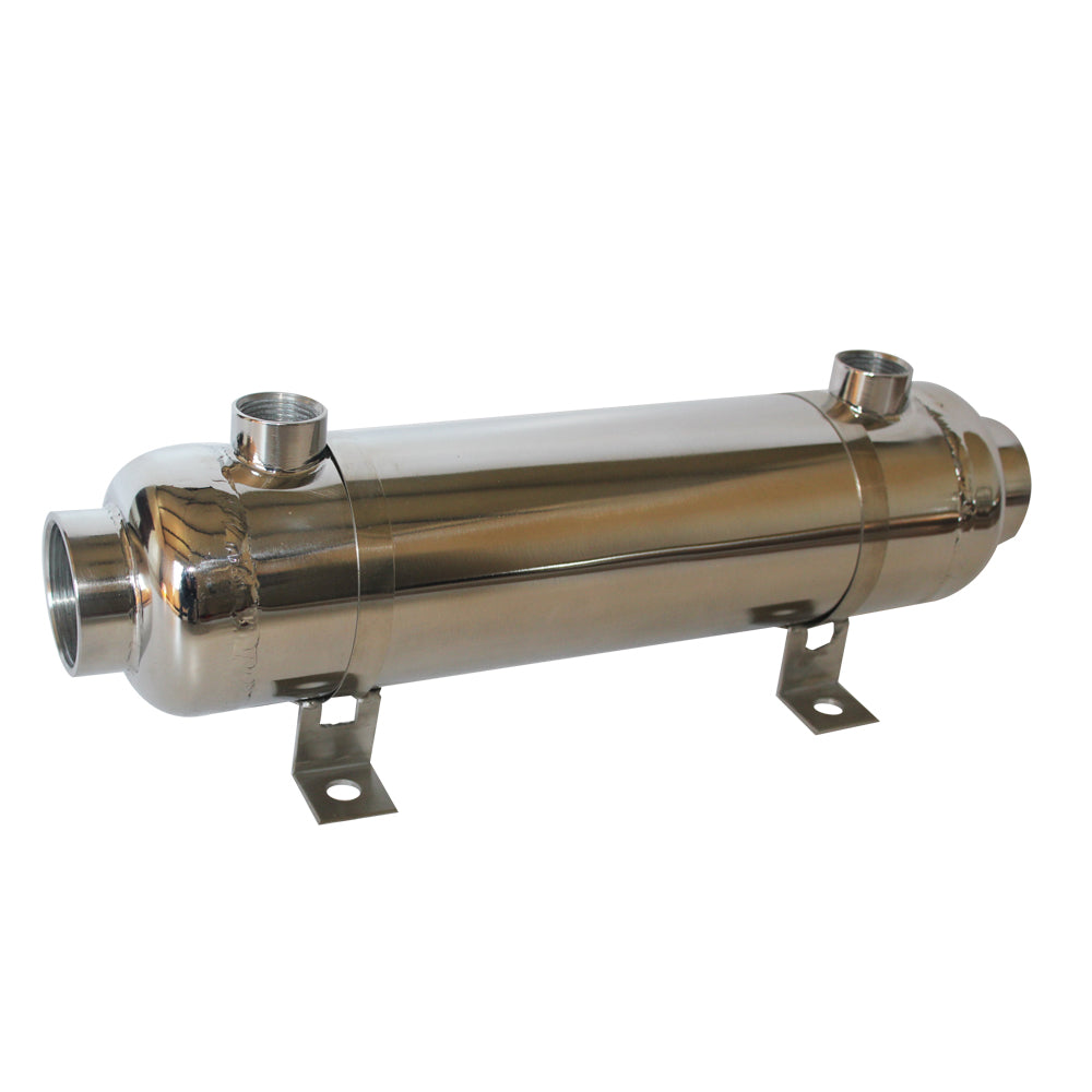
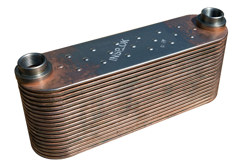
5.1 Oil Coolers (Main Engine & Auxiliary)
5.2 Fuel Oil Coolers and Viscosity Control Units
5.3 Pumps, Bypass Lines, and Flow Stability
5.4 Temperature Control Valves and Regulators
5.5 Coolers as Contamination Boundaries
5.6 Sensors, Alarms, and Control Dependencies - Control Under Real Operating Conditions
- Oil and Fuel Chemistry, Fouling, and Degradation
- Failure Development and Damage Progression
- Human Oversight, Watchkeeping, and Engineering Judgement
- Relationship to Adjacent Systems and Cascading Effects
1. System Purpose and Design Intent
Oil and fuel coolers exist to enforce viscosity control, not temperature control in isolation.
Lubricating oil must maintain a viscosity high enough to sustain hydrodynamic films under load, yet low enough to flow rapidly to bearings and cool internal components. Fuel oil must arrive at injectors within a narrow temperature window to ensure correct atomisation, penetration, and combustion timing.
Both fluids are chemically active, contamination-sensitive, and intolerant of thermal instability.
The purpose of oil and fuel coolers is therefore to:
- stabilise viscosity
- damp thermal transients
- protect downstream precision components
- preserve lubrication and combustion margins
Cooling too much is as dangerous as cooling too little. Overcooling increases viscosity, starves bearings, and destabilises injection. Undercooling collapses oil films and destroys injector geometry.
This system exists to hold a narrow operating corridor against a violently variable engine.

2. Boundaries, Interfaces, and Separation Philosophy
Oil and fuel coolers sit at the intersection of multiple systems:
- HT/LT freshwater
- seawater cooling
- lubrication
- fuel oil conditioning
- automation
They are deliberately isolated from:
- bilge systems
- freshwater domestic systems
- firemain systems
Any breach across these boundaries introduces contamination that cannot be tolerated.
Separation philosophy exists because:
- oil contaminated with water loses film strength
- fuel contaminated with seawater damages injectors instantly
- cross-contamination often propagates unnoticed
Coolers are therefore both thermal devices and chemical barriers.
3. Thermodynamic and Fluid Behaviour of Oil and Fuel
Oil and fuel behave very differently from water.
Lubricating oil:
- has lower thermal conductivity
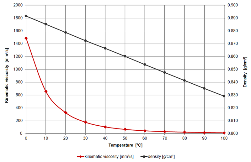
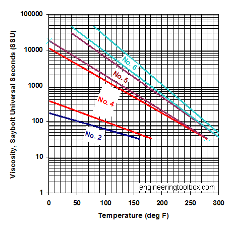
- exhibits steep viscosity–temperature curves
- traps heat internally
- degrades chemically with temperature and oxygen
Fuel oil:
- changes viscosity dramatically with temperature
- forms deposits when overheated
- suffers density changes that affect injection timing
Heat transfer through oil is inherently inefficient. This is why oil coolers must provide large surface areas, stable flow, and controlled velocity.
Thermal shock is particularly damaging. Rapid cooling thickens oil abruptly, increasing pump load and starving bearings at precisely the moment demand is highest.
Oil and fuel coolers therefore exist to smooth temperature gradients, not chase setpoints.
4. System Architecture and Flow Philosophy
4.1 Lubricating Oil Cooling Circuits
Main engine lubricating oil coolers are typically arranged:
- downstream of pumps
- upstream of bearings
- with bypass lines for minimum flow
Cooling is controlled via:
- three-way temperature control valves
- bypass arrangements
- sometimes variable-speed pumps
The objective is constant oil delivery temperature under all load conditions.
Overcooling during low-load operation is a common and dangerous condition.


4.2 Fuel Oil Cooling and Conditioning Circuits
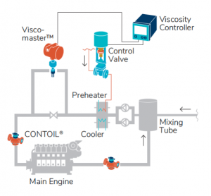
Fuel oil coolers are usually integrated into:
- viscosity control units
- fuel conditioning modules
- return-line temperature control loops
Their role is to remove excess heat added during:
- fuel heating
- circulation
- return flow from injectors
Incorrect fuel temperature directly affects:
- injection pressure
- spray pattern
- ignition delay
Fuel coolers therefore operate as precision stabilisers, not bulk coolers.

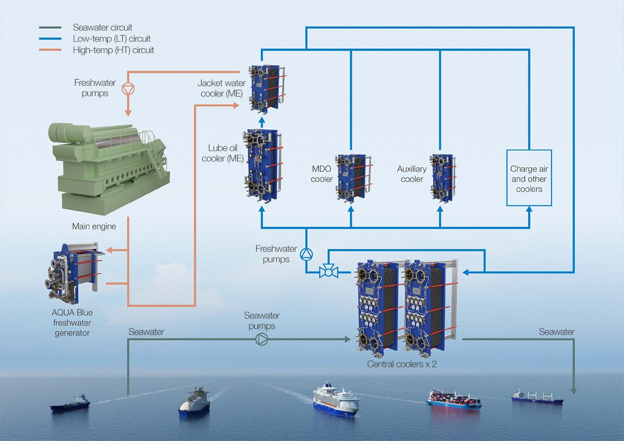
4.3 Integration with HT/LT and Seawater Systems
Oil and fuel coolers usually reject heat to:
- LT freshwater systems
- occasionally directly to seawater in smaller plants
This makes them dependent on LT system stability. Any LT temperature excursion propagates directly into oil viscosity and fuel behaviour.
They are therefore secondary victims of LT system degradation.
5. Major Machinery and Control Hardware
5.1 Oil Coolers (Main Engine & Auxiliary)
Oil coolers are typically:
- shell-and-tube
- plate-type
Common failure modes:
- fouling reducing heat transfer
- tube thinning
- internal bypassing
- gasket failure allowing water ingress
A leaking oil cooler contaminates oil silently until damage is advanced.
5.2 Fuel Oil Coolers and Viscosity Control Units
Fuel oil coolers operate in tighter tolerances than oil coolers.
Failure consequences include:
- injector needle seizure
- poor atomisation
- incomplete combustion
- exhaust valve damage
These coolers are often overlooked because failures manifest elsewhere.
5.3 Pumps, Bypass Lines, and Flow Stability
Oil pumps must maintain flow even as viscosity changes.
Bypass lines ensure minimum flow through coolers during:
- low load
- cold starts
- manoeuvring
Blocking or throttling bypasses to “improve cooling” is a common and damaging modification.
5.4 Temperature Control Valves and Regulators
Control valves regulate viscosity indirectly via temperature.
Failure modes include:
- hunting
- sticking
- incorrect manual positioning
Valves that respond too aggressively create unstable oil supply conditions.
5.5 Coolers as Contamination Boundaries
Oil and fuel coolers are pressure boundaries between:
- oil and water
- fuel and water
Any breach introduces contamination that:
- destroys lubrication films
- damages injectors
- accelerates bearing wear
Coolers are therefore risk concentrators, not neutral components.
5.6 Sensors, Alarms, and Control Dependencies
Temperature sensors do not measure viscosity. They infer it.
Sensor drift allows degradation to continue unnoticed until damage is irreversible.
Local indications often detect failure before remote alarms.
6. Control Under Real Operating Conditions
Design load is rare.
Oil and fuel cooling must cope with:
- slow steaming
- manoeuvring
- harbour running
- standby operation
Overcooling during low load is the dominant failure mode, not overheating.
Thermal inertia must be respected.
7. Oil and Fuel Chemistry, Fouling, and Degradation
Oil degrades with:
- temperature
- oxygen
- contamination
Fuel forms deposits when overheated and oxidised.
Cooling slows degradation but cannot reverse it.
Once contamination enters, damage continues even after repair.
8. Failure Development and Damage Progression
Failures are gradual:
- fouling
- loss of control margin
- rising pump load
- unstable temperatures
Catastrophic failure is usually the final stage of a long, silent decline.
9. Human Oversight, Watchkeeping, and Engineering Judgement
Automation reports numbers. Engineers recognise behaviour.
Unstable oil temperature trends, frequent valve movement, and rising pump current are early warnings that automation rarely flags.
Experience prevents damage, not alarms.
10. Relationship to Adjacent Systems and Cascading Effects
Oil and fuel cooling instability propagates into:
- bearing damage
- injector failure
- combustion instability
- exhaust valve distress
- turbocharger fouling
These systems do not fail alone.