Position in the Plant
System Group: Cooling & Heat Transfer
Primary Role: Internal thermal control of engines and critical auxiliaries
Interfaces: Seawater Cooling · Oil Cooling · Fuel Conditioning · Charge Air · Waste Heat Recovery
Operational Criticality: Continuous
Failure Consequence: Accelerated wear → combustion instability → machinery damage → loss of availability
HT and LT freshwater circuits are not support systems. They are structural systems that define the thermal condition in which all other machinery must survive.
Contents
- System Purpose and Design Intent
- Boundaries, Interfaces, and Separation Philosophy
- Thermodynamic and Physical Operating Principles
- System Architecture and Flow Philosophy
4.1 HT Freshwater Circuit
4.2 LT Freshwater Circuit
4.3 Central Cooling and Seawater Interface - Major Machinery and Control Hardware
5.1 Core Heat Exchange Equipment
5.2 Circulation Pumps and Drives
5.3 Jacket Water Heaters and Standby Thermal Integrity
5.4 Temperature Control Valves and Actuators
5.5 Expansion Tanks, Static Head, and System Geometry
5.6 Sensors, Indications, and Alarm Dependence - Control Under Real Operating Conditions
- Water Chemistry, Oxygen, and Corrosion Reality
- Failure Development and Damage Progression
- Human Oversight, Watchkeeping, and Engineering Judgement
- Relationship to Adjacent Systems and Cascading Effects
1. System Purpose and Design Intent
HT and LT freshwater circuits exist to impose order on heat.
Internal combustion engines generate heat unevenly, violently, and continuously. Without controlled heat removal, local temperatures would exceed metallurgical limits long before global alarms reacted. Freshwater cooling allows engine designers and operators to shape thermal behaviour, rather than simply survive it.
The intent is not maximum cooling. It is controlled temperature stability.
Cylinder liners, cylinder heads, exhaust valve cages, and fuel injection components require high, stable metal temperatures to prevent cold corrosion, acid condensation, liner polishing, and distortion. At the same time, lubricating oil, charge air, and fuel conditioning systems demand low, tightly controlled temperatures to preserve viscosity, density, and material limits.
No single cooling circuit can satisfy both demands. HT and LT circuits exist because thermal priorities conflict, and separation is the only way to prevent one consumer destabilising another.
Freshwater, not seawater, is used internally because:
- Its chemistry can be controlled
- Its oxygen content can be limited
- Its corrosion rate is slower and predictable
- Its boiling behaviour is manageable via static head
This system defines the thermal environment in which engines live their entire service life.
2. Boundaries, Interfaces, and Separation Philosophy
HT and LT systems are deliberately isolated from:
- Seawater
- Bilge systems
- Firefighting systems
- Domestic freshwater
These boundaries are not arbitrary. They exist because contamination is irreversible in practice, even if repair is possible on paper.
The HT circuit serves engine structure.
The LT circuit serves engine services.
If LT demand were allowed to influence HT temperature directly, any sudden change in oil cooling load or charge air demand would immediately destabilise liner and head temperatures. That instability manifests as:
- uneven thermal expansion
- bore distortion
- head gasket movement
- micro-cracking long before alarms
Separation enforces hierarchy. HT temperature stability always takes precedence over auxiliary cooling demand.
Interfaces between HT and LT are therefore limited, deliberate, and controlled — most commonly through heat cascade, not mixing.
3. Thermodynamic and Physical Operating Principles
HT cooling operates close to material limits. This is intentional.
High HT temperatures:
- reduce sulphuric acid formation
- keep liner walls above dew point
- stabilise combustion chamber geometry
- reduce thermal cycling fatigue
The goal is not “cool enough”, but “consistently hot enough.”
LT cooling, by contrast, acts as a thermal buffer. It absorbs rejected heat from oil coolers, charge air coolers, fuel heaters, and auxiliary machinery, then rejects that heat onward to seawater via central coolers.
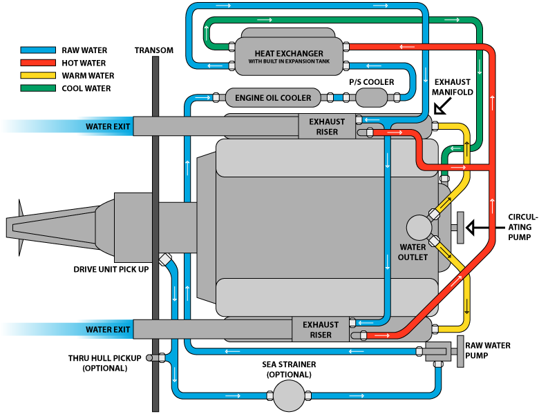
In modern plants, heat flow is often:
HT → LT → Seawater
This cascade:
- reduces thermal shock
- smooths temperature transients
- isolates engine structure from seawater variability
Pressure, not just temperature, matters. Static head determines boiling margin. Local pressure drop at hot spots can trigger nucleate boiling even when bulk temperatures appear normal.
Thermodynamics does not forgive optimism.

4. System Architecture and Flow Philosophy
4.1 HT Freshwater Circuit
The HT circuit typically flows through:
- cylinder jackets
- cylinder heads
- exhaust valve cooling passages
- occasionally turbocharger bearing housings
Flow is continuous and deliberately slow enough to allow heat pickup without inducing erosion or vibration.
A three-way temperature control valve governs whether HT water passes through the HT cooler or bypasses it. This valve is not chasing a temperature number; it is controlling rate of change.
Rapid cooling is structurally dangerous. Metal contracts unevenly. Liners distort. Gaskets extrude. Damage occurs silently.

4.2 LT Freshwater Circuit
The LT circuit serves multiple consumers simultaneously:
- lubricating oil coolers
- charge air coolers
- fuel oil coolers
- auxiliary machinery
LT demand is volatile. It responds instantly to:
- engine load
- ambient seawater temperature
- manoeuvring
- auxiliary start/stop events
As a result, LT systems prioritise responsiveness over inertia. Instability here propagates rapidly into oil viscosity loss, charge air density reduction, and fuel temperature excursions.
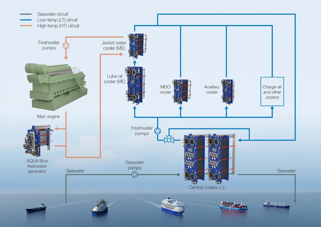
4.3 Central Cooling and Seawater Interface
The central cooler is the most critical boundary in the entire cooling plant.
Here, conditioned freshwater meets corrosive seawater across thin metallic walls. Any breach introduces chlorides into the freshwater system. Once chlorides enter, corrosion accelerates internally and cannot be fully arrested by chemical treatment alone.
Central coolers are consumable components. Treating them as permanent assets is an accounting fiction.
5. Major Machinery and Control Hardware
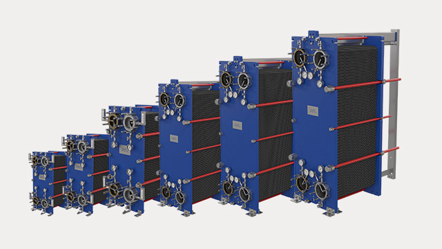
5.1 Core Heat Exchange Equipment
HT coolers, LT coolers, and central coolers define the heat rejection ceiling of the plant.
Fouling does not immediately raise temperature — it erodes margin. By the time alarms appear, the system is already operating without reserve.
Plate coolers suffer from:
- gasket degradation
- plate deformation
- internal bypassing
Shell-and-tube coolers suffer from:
- tube thinning
- erosion
- crevice corrosion
A cooler that “still works” may already be finished.
5.2 Circulation Pumps and Drives
HT pumps protect metal integrity.
LT pumps protect oil, fuel, and air systems.
Common degradation paths include:
- seal air ingress
- impeller erosion
- cavitation at local hot spots
- air locking during changeover
Pump changeover is a high-risk operation, not a routine one.
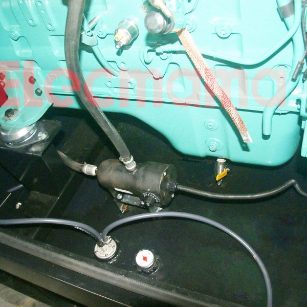
5.3 Jacket Water Heaters and Standby Thermal Integrity
Jacket water heaters maintain thermal equilibrium during shutdown and standby.
Their role is not comfort — it is metallurgical protection.
Cold soaking causes:
- liner shrinkage
- bore distortion
- oil film collapse
- increased starting air demand
- unstable initial combustion
Heaters are electrically simple but thermally critical. They are often isolated to “save power” and only remembered when the engine refuses to start cleanly.
5.4 Temperature Control Valves and Actuators
These valves determine system stability, not just temperature.
Failure modes include:
- spindle sticking
- actuator hunting
- incorrect tuning
- manual locking in fixed positions
A valve that responds too quickly is as dangerous as one that does not respond at all.
5.5 Expansion Tanks, Static Head, and System Geometry
Expansion tanks provide:
- volume compensation
- air separation
- static head
Static head defines boiling margin. Insufficient elevation allows nucleate boiling at exhaust valve seats even when temperatures appear normal.
The expansion tank is a diagnostic instrument, not just a reservoir.
5.6 Sensors, Indications, and Alarm Dependence
Automation depends entirely on sensor accuracy.
Sensor drift masks degradation.
False stability is more dangerous than visible instability.
Local gauges often tell the truth before the control room does.
6. Control Under Real Operating Conditions
Design conditions are rare at sea.
Manoeuvring, slow steaming, harbour running, and standby operation impose transient thermal states. The danger lies not in absolute temperature, but in thermal gradient and rate of change.
Automation reacts to numbers. Engineers interpret trends.
7. Water Chemistry, Oxygen, and Corrosion Reality
Chemical treatment slows corrosion; it does not stop it.
Oxygen ingress through leaks, poor venting, or maintenance errors accelerates attack. Chloride ingress overwhelms inhibitors entirely.
Once contaminated, systems degrade from the inside out.
8. Failure Development and Damage Progression
HT/LT failures develop quietly:
- fouling
- air accumulation
- valve drift
- cross-contamination
The most dangerous condition is a system that still “holds temperature” while operating at the edge of its control envelope.
9. Human Oversight, Watchkeeping, and Engineering Judgement
Automation masks deterioration. Engineers detect it.
A plant running with valves fully open, pumps at maximum, and coolers marginally effective is not stable — it is one disturbance away from failure.
Judgement, not alarms, prevents damage.
10. Relationship to Adjacent Systems and Cascading Effects
HT/LT instability propagates into:
- lubrication breakdown
- fuel viscosity errors
- charge air density loss
- refrigeration inefficiency
- waste heat recovery imbalance
Without mastery of freshwater cooling, no meaningful understanding of shipboard heat transfer is possible.