Principles, Operation, Design & Marine Application
Engine Room · Core Machinery · Fundamentals
Introduction
Four-stroke marine engines are the workhorses of shipboard power generation and, in many vessel types, medium-speed propulsion. They dominate applications where ships require:
- Reliable electrical generation (diesel generators / gensets)
- Rapid response to variable load demand
- Compact machinery suitable for limited engine-room space
- Modular maintenance and cylinder-level accessibility
Four-stroke engines are found on:
- Most merchant vessels (auxiliary generators)
- Offshore vessels (highly variable and transient loads)
- Ferries and tugs (often both propulsion and power generation)
- Cruise ships (multiple gensets supplying electric propulsion and hotel load)
- Smaller cargo vessels and workboats (medium-speed propulsion)
This page is the authoritative home reference for four-stroke marine engines on MaritimeHub. It explains how they work, why they are designed the way they are, and how marine engineers should think about them during operation, monitoring, and fault diagnosis.
Contents
- What Defines a Four-Stroke Marine Engine
- Why Four-Stroke Engines Dominate Auxiliary Power
- The Four-Stroke Operating Cycle (Step-by-Step)
- Valve Timing & Gas Exchange (Concept Level)
- Air Supply, Turbocharging & Charge-Air Cooling
- Fuel Injection & Combustion Behaviour
- Lubrication Systems (Trunk Piston Philosophy)
- Cooling Systems & Thermal Control
- Mechanical Design: Trunk vs Crosshead, Medium-Speed Layout
- Governing, Load Sharing & Generator Behaviour
- Operational Behaviour at Sea
- Sensitivity to Load, Fuel Quality & Maintenance Condition
- Common Misconceptions About Four-Stroke Engines
- How This Page Anchors the Four-Stroke Section
1. What Defines a Four-Stroke Marine Engine
1.1 Principle
A four-stroke engine completes one full thermodynamic cycle over two crankshaft revolutions (720°). Each cylinder performs the following strokes in sequence:
- Intake
- Compression
- Power (combustion)
- Exhaust
As a result, one power stroke occurs every second crankshaft revolution.
1.2 Defining Characteristics
Most marine four-stroke engines are:
- Medium-speed (typically ~300–1,000 RPM, depending on application)
- Multi-cylinder, inline or V-configuration
- Valve-controlled gas exchange (camshaft, pushrods/rockers or overhead cams)
- Turbocharged with charge-air cooling
- Commonly coupled to alternators with load-sharing capability
Four-stroke engines are valve-timed breathing machines.
Their efficiency, stability, emissions, and longevity depend heavily on valve events, air handling, and combustion quality.

2. Why Four-Stroke Engines Dominate Auxiliary Power
2.1 Engineering Intent
Four-stroke engines are selected where a vessel requires:
- Rapid response to load changes
- Stable operation across a wide load range
- High power density in compact machinery spaces
- Modular maintenance and cylinder-level access
- Proven compatibility with electrical generators and load-sharing systems
2.2 Marine Reality
Shipboard electrical demand is rarely constant and commonly includes:
- Thrusters during manoeuvring
- Reefer container loads
- Cargo handling equipment
- HVAC and hotel load (especially on cruise vessels)
- Dynamic positioning (DP) systems offshore
Four-stroke gensets are designed to handle continuous load variation reliably.
A two-stroke main engine prefers steady propeller load.
A four-stroke generator is optimised for variable electrical demand.
3. The Four-Stroke Operating Cycle (Step-by-Step)
Overview
The four-stroke cycle is defined by piston motion and valve events over 720° of crankshaft rotation.
3.1 Intake Stroke (0°–180°)
- Piston: moves down (TDC → BDC)
- Valves: intake open, exhaust closed
- Process: fresh air enters the cylinder (naturally aspirated or turbocharged)
Cylinder filling depends on:
- Intake valve timing
- Manifold pressure
- Turbocharger and aftercooler condition
- Air filter and intake restrictions
3.2 Compression Stroke (180°–360°)
- Piston: moves up (BDC → TDC)
- Valves: both closed
- Process: air is compressed, raising pressure and temperature
Compression quality governs:
- Ignition delay
- Peak combustion pressure
- Starting performance
- Overall efficiency
Weak compression often shows as smoke, uneven firing, or high exhaust temperatures — not simply “won’t start”.
3.3 Power Stroke (360°–540°)
- Piston: moves down (TDC → BDC)
- Valves: both closed (until exhaust opens near end)
- Process: fuel is injected, ignites, and expanding gases do work
Key influences:
- Injection timing and rate
- Atomisation quality
- Pressure rise rate (mechanical stress and noise)
3.4 Exhaust Stroke (540°–720°)
- Piston: moves up (BDC → TDC)
- Valves: exhaust open, intake closed
- Process: exhaust gases expelled
Exhaust effectiveness influences:
- Residual gas fraction
- Next-cycle combustion stability
- Turbocharger energy availability
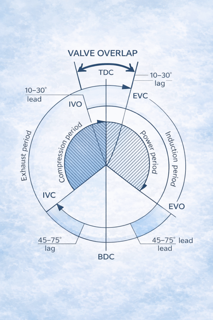
4. Valve Timing & Gas Exchange (Concept Level)
4.1 What “Timing” Means
Valve timing defines:
- When valves open and close relative to piston position
- Valve overlap between intake and exhaust
- Overall breathing efficiency
Typical features include:
- Intake opening before TDC
- Exhaust closing after TDC
- Controlled valve overlap to improve scavenging and turbo response
4.2 Why Engineers Care
Valve timing directly affects:
- Volumetric efficiency
- Exhaust temperature
- Turbocharger performance
- Smoke tendency and emissions
📌 Detailed timing diagrams, cam profiles, and valve gear designs are covered in dedicated Engine Room pages.
5. Air Supply, Turbocharging & Charge-Air Cooling
5.1 Principle
Most marine four-stroke engines are turbocharged to:
- Increase air mass in the cylinder
- Improve power density
- Reduce specific fuel consumption
- Support cleaner combustion
5.2 Charge-Air Cooling
Compressed air leaving the turbocharger is hot. Charge-air coolers (aftercoolers) reduce temperature and increase air density.
Poor charge-air cooling results in:
- Higher intake temperatures
- Reduced oxygen availability
- Higher exhaust temperatures
- Increased smoke and NOₓ
Air problems often masquerade as fuel problems. Always verify air first.
6. Fuel Injection & Combustion Behaviour
6.1 Injection Philosophy
Four-stroke marine engines use:
- Mechanical pump-and-cam systems (traditional)
- Common-rail systems (modern)
- Electronically controlled injection with variable timing and rate shaping
Fuel is injected near the end of the compression stroke, shortly before TDC.
6.2 Ignition Delay & Mixture Preparation
After injection begins, a short ignition delay occurs during which:
- Fuel jets atomise into droplets
- Droplets absorb heat and vaporise
- Fuel vapour mixes with compressed air
Ignition occurs once the mixture reaches the fuel’s auto-ignition temperature.
6.3 Phases of Diesel Combustion (Conceptual)
Diesel combustion is commonly described in three overlapping phases:
- Premixed combustion – rapid burning of fuel prepared during ignition delay
- Mixing-controlled (diffusion) combustion – dominant phase, governed by air–fuel mixing
- Late burn-out – oxidation of remaining hydrocarbons and soot
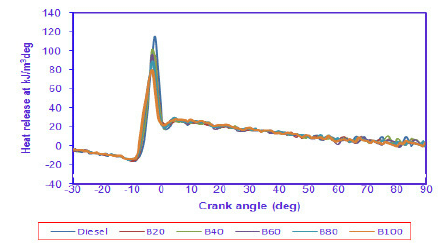
Heat-release rate vs crank angle showing premixed and diffusion phases
6.4 Air–Fuel Ratio & Excess Air
Diesel engines operate with a lean overall air–fuel ratio:
- Stoichiometric ≈ 14.4:1
- Typical diesel operation:
- Peak torque: >25:1
- Idle (turbocharged): may exceed 160:1
Much of the air inducted never participates in combustion, helping limit temperatures and reduce smoke.
Combustion quality depends on every system that influences air or fuel, not just injectors.
📌 Detailed combustion optimisation and emissions strategies are covered in dedicated pages.
7. Lubrication Systems (Trunk Piston Philosophy)
7.1 Core Difference vs Two-Stroke
Most marine four-strokes use a trunk piston design, meaning:
- The crankcase and piston underside share the same space
- A single system oil lubricates bearings, piston skirts, and cylinder walls
7.2 Oil Responsibilities & Risks
System oil must provide:
- Lubrication film strength
- Bearing cooling
- Contamination control (soot, fuel dilution, water)
Key risks include:
- Fuel dilution reducing viscosity
- Soot loading accelerating wear
- Water contamination damaging bearings
“Oil looks fine” is not data. Trend viscosity, BN/TBN, insolubles, and water content.
8. Cooling Systems & Thermal Control
Four-stroke engines typically use:
- Jacket water cooling (block and head)
- Lube oil cooling
- Charge-air cooling
- Sometimes separate HT/LT circuits
Thermal control affects:
- Efficiency
- Wear rates
- Combustion stability
- Emissions
Running too cold increases deposits and smoke; running too hot accelerates oil breakdown and component stress.
9. Mechanical Design: Trunk vs Crosshead, Medium-Speed Layout
9.1 Typical Construction
Common elements include:
- Inline or V-block
- Camshaft-driven valve gear
- Turbocharger and aftercooler
- Reduction gearbox (if used for propulsion)
- Resilient mounts or rigid foundation
9.2 Trunk Piston Implications
Trunk piston design results in:
- Higher side thrust on liners than crosshead engines
- Greater sensitivity to lubrication quality
- More direct impact of oil contamination on engine internals
Four-strokes trade the size and low speed of two-strokes for compactness and responsiveness.
10. Governing, Load Sharing & Generator Behaviour
10.1 Why Governing Matters
Four-stroke gensets must maintain:
- Speed (frequency)
- Voltage (via AVR)
- Stable load sharing between multiple units
Key concepts include:
- Droop vs isochronous control
- kW (active power) sharing
- kVAr (reactive power) sharing
10.2 Operational Symptoms
Poor governing or load sharing appears as:
- Hunting or RPM oscillation
- Uneven kW load distribution
- Breaker trips
- Frequency instability during load steps
📌 Detailed governor tuning and synchronisation are covered in Electrical/Power pages.
11. Operational Behaviour at Sea
Four-stroke engines:
- Tolerate variable loads better than two-strokes
- Respond quickly to load steps
- Require attention to thermal stabilisation during start/stop
- Are sensitive to maintenance condition
Watchkeeping mindset:
Trend exhaust temperatures, oil pressure/temperature, charge-air temperature and ΔP, jacket water temperature, and smoke behaviour.
12. Sensitivity to Load, Fuel Quality & Maintenance Condition
Four-strokes may run acceptably while gradually degrading due to:
- Injector wear
- Valve leakage
- Turbo and aftercooler fouling
- Air restriction
- Fuel contamination
- Lube oil dilution
High-risk operating regimes include:
- Prolonged low load (wet stacking)
- Frequent start/stop cycles
- Rapid load changes without stabilisation
Many “random” four-stroke problems are the result of operating regime plus gradual fouling.
13. Common Misconceptions About Four-Stroke Engines
❌ “Four-strokes are always easier than two-strokes”
✔ Often easier mechanically, but more sensitive to valves, injection, and load response
❌ “If it holds frequency, it’s healthy”
✔ It can hold frequency while overheating or wearing internally
❌ “Smoke is normal on load change”
✔ Brief smoke may be acceptable; persistent smoke is diagnostic information
14. How This Page Anchors the Four-Stroke Section
This page is the conceptual foundation for all four-stroke content on MaritimeHub.
All related topics link back here, including:
- Fuel systems and injection
- Valve gear and timing
- Turbocharging and air systems
- Lubrication and oil analysis
- Cooling systems
- Governing, synchronisation, and load sharing
- Faults and troubleshooting
A marine four-stroke engine is a controlled breathing and combustion machine.
If you understand air handling, valve timing, mixture preparation, and load response, you can diagnose most faults before alarms occur.
Tags
four-stroke marine engine · marine diesel generator · medium-speed diesel · valve timing · turbocharging · load sharing · engine room fundamentals