ENGINE ROOM → Control & Operations
Position in the Plant
System Group: Control & Operations
Primary Role: Shared situational awareness and command authority between bridge and machinery spaces
Interfaces: IAS/AMS · PMS · Propulsion control · Steering · Navigation sensors · Fire & Gas · Cargo (where fitted) · Power distribution
Operational Criticality: High
Failure Consequence: Loss of coordinated control → wrong response timing → blackout escalation, propulsion/steering errors, unsafe manoeuvring, delayed emergency actions
Bridge–engine interfaces are not “screens”.
They are the coordination layer that decides whether the ship behaves like one plant or two competing worlds.
When they work well, the bridge can command with context and the engine room can act with intent.
When they degrade, the ship becomes a set of disconnected subsystems, each making locally reasonable decisions that can be globally unsafe.
Contents
- Why Bridge–Engine Interfaces Exist
- Authority, Responsibility, and Control Boundaries
- Data Paths and Protocol Reality
- What the Bridge Actually Needs to See
- What the Engine Room Needs to Trust About the Bridge
- Alarm Transfer, Acknowledgement, and “Split-Brain” Failure
- Propulsion and Manoeuvring Interfaces
- Power Generation and PMS Interfaces
- Tank, Bilge, and Transfer Interfaces
- Fire Detection, Safety, and Emergency Signalling
- Human Factors: Workload, Overconfidence, and Misleading Screens
- Failure Modes, Symptoms, and Shipboard Diagnostics
- Operational Discipline: Tests, Change Control, and Watchkeeping Practice
1. Why Bridge–Engine Interfaces Exist
The bridge operates the vessel in space.
The engine room operates the vessel in physics.
The interface exists because the bridge must make decisions that depend on machinery condition—often under time pressure—while the engine room must respond to bridge intent without ambiguity.
On a modern vessel, the bridge is no longer “just orders via telegraph”. It is commonly tied into:
- propulsion control and pitch/shaft commands
- power management status and load margins
- steering and thruster availability
- alarms and event logging
- occasionally tank monitoring, fire zones, and ship services
This integration is not primarily for convenience. It is a safety architecture designed to prevent delayed awareness and uncoordinated actions.
2. Authority, Responsibility, and Control Boundaries
A bridge–engine interface must define who has authority over what, and under which conditions that authority can transfer.
The most dangerous interface is the one that appears to give control while hiding the true boundary conditions.
Three realities must be explicit:
Command is not the same as control.
The bridge may command rpm or pitch, but control loops are executed in machinery controllers, with protections that may override commands.
Local safety interlocks win.
Trips, shutdowns, ESD logic, overspeed protections, LO low pressure trips, and thermal limits will override the bridge every time. This is correct.
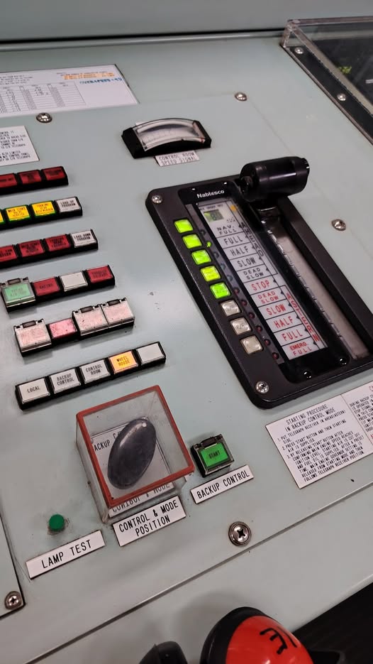
Control transfer is a hazardous operation.
Bridge control → ECR control → local control is not a checkbox. It can introduce step changes in demand, transient instability, and confusion during manoeuvring.
A properly designed interface makes control mode unambiguous, visible, and alarmed.
3. Data Paths and Protocol Reality
Most failures in “bridge monitoring” are not sensor failures.
They are translation failures and transport failures.
Modern ships commonly bridge multiple protocol families:
- CAN bus / J1939 for engine and generator ECU data (RPM, pressures, temperatures, load, alarms)
- Modbus (RTU/TCP) for power meters, battery systems, VFDs, HVAC plants, and auxiliaries
- NMEA 2000 / NMEA 0183 primarily for navigation and some integrated machinery display networks
- Ethernet/IP or proprietary networks for IAS/AMS, PMS, and integrated automation systems
A “bridge interface module” is often a translator: it takes engine ECU data (J1939/CAN) and converts it into a format the bridge can display (commonly NMEA 2000 or a vendor proprietary integration layer). Similar bridging happens for Modbus-connected systems.
This translation introduces three degradations:
Latency
Values displayed on the bridge may be seconds behind reality under network load.
Averaging and smoothing
Displayed values are often filtered, hiding spikes that matter operationally.
Semantic mismatch
One system’s “alarm” may be another system’s “warning”, or an ECU fault code may be simplified into a generic message.
A bridge display is therefore not a truth source.
It is a representation produced by a chain of devices, each with failure modes.
4. What the Bridge Actually Needs to See
Bridge displays should not attempt to mirror the ECR mimic.
They should surface decision-grade parameters: the minimum information required to manoeuvre safely and respond correctly.
That set usually includes:
Propulsion health and limits
Available ahead/astern, pitch limits, rpm limits, torque/load limits, mode status, active protections (e.g., load limitation, clutch inhibit, overspeed protection armed).
Cooling and lube essentials
Not full cooling system diagrams—just the parameters that define whether propulsion is being operated inside safe margins: LO pressure/temperature, HT/LT temperatures, jacket water status, sea water cooling boundary status.
Power margin
Generator online count, load %, spinning reserve, PMS mode, blackout recovery mode armed, major consumers running (thrusters, cargo pumps, large HVAC, reefers).
Thruster availability and constraints
Ready/not ready, power limit, overheating, drive fault status, command acceptance status.
Alarm summary that is prioritised
Not the entire alarm list—only those alarms that demand bridge action, especially during manoeuvring.
The bridge does not need every sensor.
It needs the limits and the reasons limits are being applied.
5. What the Engine Room Needs to Trust About the Bridge
From the machinery side, the risk is not that the bridge lacks information.
The risk is that the bridge thinks it has control when the plant is already imposing constraints.
Engine room personnel need assurance that bridge commands are:
- received (communications integrity)
- interpreted correctly (no unit mismatch, no wrong scaling)
- executed within known limitations (load control, torque limiting, clutch logic)
- visible in the ECR as demand signals (traceability)
The interface must support diagnosis, not just operation. When something behaves oddly, engineers must be able to identify whether:
- the bridge demand is unstable
- the control mode has shifted
- a limiter is active
- a PLC is substituting default values due to comms loss
This requires the interface to expose mode state and limiter state, not just numbers.
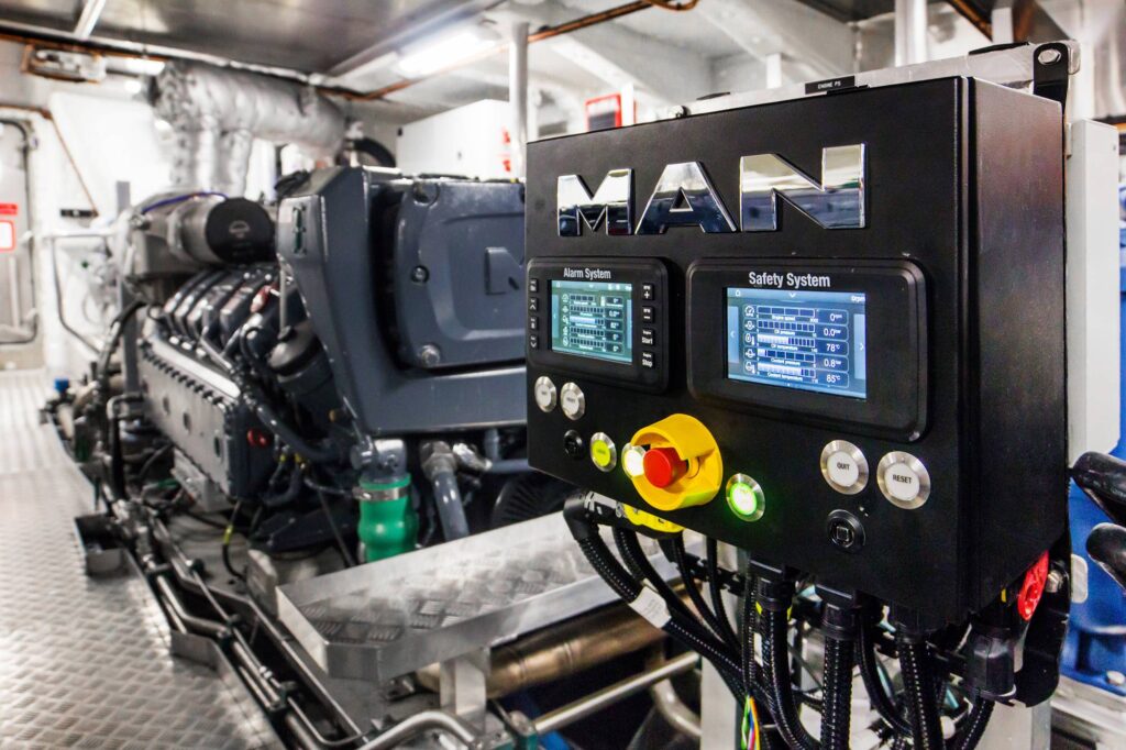
6. Alarm Transfer, Acknowledgement, and Split-Brain Failure
Alarm routing between engine room and bridge is one of the most misunderstood areas.
There are typically three alarm “worlds”:
- ECU alarms (engine/generator controller)
- IAS/AMS alarms (automation system)
- bridge alarm display and summarisation
If alarm transfer is not engineered properly, you get a split-brain condition:
- the bridge acknowledges an alarm that the ECR still considers active
- the ECR sees an alarm, but the bridge receives only a generic “fault”
- alarm floods occur on the bridge during manoeuvring, leading to silencing behaviour
Acknowledgement must be designed with intent. In many plants:
- acknowledgement at the bridge acknowledges the display, not the alarm state
- clearing requires process return-to-normal or ECR reset
- critical alarms require local verification before reset
If the bridge can “clear” alarms that machinery staff still consider unsafe, the interface becomes dangerous.
7. Propulsion and Manoeuvring Interfaces
This is where interface quality is exposed immediately.
During manoeuvring, propulsion demand changes quickly and unpredictably. A bridge–engine interface must manage:
Command authority
Is the bridge commanding directly, or commanding via an ECR-set limiter or mode?
Response shaping
Rapid pitch changes can induce torque spikes, clutch stress, and transient overloads. The system may intentionally slow response. The bridge must understand when it is being rate-limited.
Clutch and gearbox interlocks
Clutch engagement logic may block commands until shaft speed and oil pressure conditions are satisfied. A bridge display that only shows “astern not available” without cause drives unsafe decision-making.
Feedback truth
Bridge must see not only “commanded pitch/rpm” but “achieved pitch/rpm”, and the delta must be meaningful. Otherwise you get phantom control: the bridge thinks it has applied astern, but the system is inhibited.
A reliable interface makes “why not” visible.
8. Power Generation and PMS Interfaces
Power is the invisible constraint on every other system.
Bridge-level power awareness matters most when:
- thrusters are used
- DP modes are active (if fitted)
- manoeuvring with high hotel load (passenger vessels)
- cargo systems are running near port
A good bridge interface shows:
- generators online and available capacity
- spinning reserve or load margin
- PMS mode (automatic, split bus, harbour mode, emergency mode)
- active load shedding stage (if any)
- large consumer status (thrusters, cargo pumps, bow thruster drives)
The bridge does not need switchboard detail.
It needs to know whether a manoeuvre request will trip the plant.
9. Tank, Bilge, and Transfer Interfaces
Where ships integrate service systems into bridge displays, the risk is misinterpretation rather than lack of information.
Tank levels, bilge alarms, and transfer states are valuable because they indicate evolving hazards:
- ballast transfer affecting trim during confined navigation
- bilge high level alarms indicating flooding risk
- fuel transfer states affecting stability and fire risk
- sludge/bilge transfer suggesting compliance risk (inappropriate timing)
But these systems are also prone to:
- sensor drift and false levels
- air-lock and piping configuration errors
- operator mode mistakes (wrong tank line-up)
The bridge should see states and alarms, not be encouraged to operate transfer systems casually without engineering oversight.
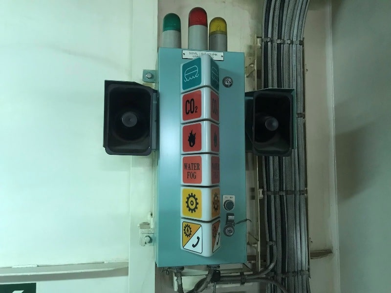
10. Fire Detection, Safety, and Emergency Signalling
Bridge–engine integration often includes:
- fire zone indication
- engine room ventilation status
- damper status
- fire pump availability
- emergency shutdown status
- PA/GA activation
The aim is not to give the bridge “engineering control”.
It is to prevent delays in command decisions during emergencies.
A fire alarm that identifies only “engine room” is operationally weak. A system that identifies a zone and time evolution supports correct response: mustering, boundary cooling decisions, ventilation actions, and ESD escalation.
11. Human Factors: Misleading Screens
Bridge displays are often treated as authoritative because they look clean.
That is a trap.
A bridge display may show:
- a stable temperature (filtered)
- a normal pressure (averaged)
- “OK” status (derived logic)
Meanwhile the machinery is experiencing:
- transient cavitation
- unstable suction conditions
- spikes masked by sample rate
- sensor drift producing false confidence
This is why good interface design includes:
- timestamping or “data age” flags
- comms-loss annunciation
- limiter state visibility
- mode and control transfer status
- ability to drill down to raw values where needed
The bridge should not be forced to interpret the entire plant.
But it must not be misled into false certainty.
12. Failure Modes, Symptoms, and Shipboard Diagnostics
Bridge–engine interface failures often present as “random behaviour”. In reality they follow repeatable patterns:
1) Comms loss / degraded bus
Symptoms: frozen values, stale alarms, delayed response, sudden reversion to defaults.
2) Protocol translation error
Symptoms: wrong units (bar vs kPa), inverted scaling, wrong source mapping (e.g., gen #2 shown as #3), missing alarms.
3) Mode confusion
Symptoms: command accepted but not executed; control transfer not truly transferred; bridge thinks it is in control but ECR/local has authority.
4) Alarm summarisation failure
Symptoms: alarm flood, critical alarms buried, nuisance alarms dominate.
5) Time synchronisation issues
Symptoms: event logs out of order, impossible fault reconstruction after incident.
Diagnostics onboard must be practical:
- verify mode at physical transfer panel
- compare bridge value with local gauge or ECR raw value
- check comms status indicators and “data age”
- confirm ECU alarms locally at controller screen
- treat the bridge display as a client, not a sensor
13. Operational Discipline
The interface is not maintained by good intentions. It is maintained by discipline.
Minimum practice on well-run ships includes:
- routine verification of bridge machinery page during manoeuvring prep
- control transfer drills with explicit call-and-response
- periodic comms-loss simulation (where permitted) to confirm alarms and default behaviour
- change control for software updates and mapping changes
- post-incident log preservation (VDR + AMS historian + PMS logs)
A bridge–engine interface becomes most valuable after something goes wrong, because the timeline must be reconstructed.
If timestamps are wrong, mappings are inconsistent, or data is filtered into uselessness, the ship loses its ability to learn.
Closing Reality
Bridge–engine interfaces exist to prevent two failures:
- the bridge manoeuvring blind
- the engine room acting without knowing intent
They are not about convenience.
They are about shared truth under time pressure.
A bridge display is only as honest as its data chain.
A command is only as safe as its control boundaries.
And the interface is only as reliable as the ship’s discipline in maintaining, testing, and understanding it.