Hydrodynamic Load, Cavitation Reality, and the Consequences of Thrust Mismanagement
ENGINE ROOM → Propulsion & Transmission
System Group: Propulsion
Primary Role: Conversion of shaft power into controlled axial thrust
Interfaces: Main Engine · Gearbox · Shafting · Bearings · Steering · Hull Form
Operational Criticality: Continuous
Failure Consequence: Load instability → vibration → bearing distress → loss of propulsion
Propellers are not passive rotating discs.
They are hydrodynamic machines that define how every upstream component is loaded, stressed, and ultimately damaged.
Position in the Plant
The propeller is the final energy conversion element in the propulsion chain. Everything upstream — combustion, torque generation, gear reduction, shaft alignment, bearing support — exists solely to deliver power to the propeller in a form it can accept.
From an engineering perspective, the propeller determines:
- the engine load curve
- the margin between normal operation and overload
- the vibration signature of the shaftline
- the fatigue life of bearings, seals, and structure
A propulsion plant cannot be understood in isolation from its propeller. Many faults diagnosed as “engine problems” originate hydrodynamically at the propeller disc.

Contents
Propeller Purpose and Design Intent
Fixed-Pitch and Controllable-Pitch Philosophy
Hydrodynamic Loading and Wake Interaction
Cavitation as an Operating Condition, Not an Anomaly
Damage Patterns and Their Mechanical Consequences
Pitch Control, Overload, and Mismatch
Control Under Real Operating Conditions
Failure Development and Progression
Human Oversight and Engineering Judgement
1. Propeller Purpose and Design Intent
A propeller converts rotational mechanical energy into thrust by accelerating a mass of water astern. The reaction force produces forward motion. This process is continuous, non-linear, and sensitive to flow conditions.
The design intent is not maximum thrust.
It is predictable thrust for a known torque input.
Every propeller is designed around a specific operating point defined by:
- vessel displacement
- service speed
- shaft RPM
- wake field characteristics
Outside this point, efficiency declines and mechanical consequences rise. The propeller does not “forgive” poor matching; it transmits the penalty upstream as torque fluctuation, vibration, and thermal stress.
2. Fixed-Pitch and Controllable-Pitch Philosophy
Fixed-Pitch Propellers (FPP)
Fixed-pitch propellers have blades of constant geometry. Their hydrodynamic characteristics are locked at manufacture.
They offer:
- mechanical simplicity
- high structural robustness
- predictable long-term behaviour
But they also impose rigidity. All speed control is achieved through RPM change alone. At low speed, engines are often forced into unfavourable operating regions where combustion quality, scavenge air supply, and turbocharger efficiency deteriorate.
From an engineering standpoint, FPP installations live or die by correct design-stage matching. Once installed, correction options are limited and expensive.
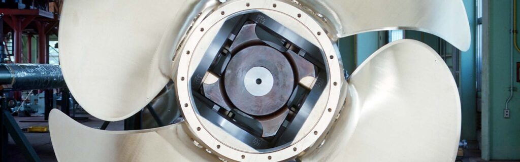
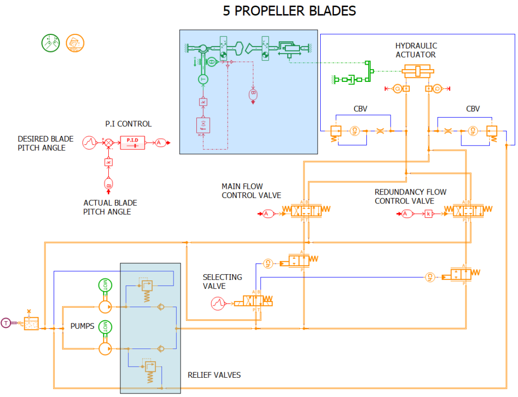
Controllable-Pitch Propellers (CPP)
CPP systems separate thrust control from shaft speed. Blade angle, not RPM, becomes the primary control variable.
This enables:
- rapid thrust reversal
- fine manoeuvring control
- constant-speed engine operation
But this flexibility comes at a cost. CPP hubs are complex hydraulic machines operating under centrifugal force, cyclic stress, and contaminated environments. Seal degradation, internal leakage, and control drift are not theoretical risks — they are expected failure modes.
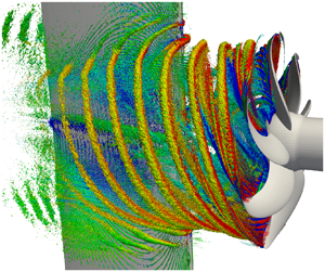
3. Hydrodynamic Loading and Wake Interaction
Propellers do not operate in uniform flow. Hull form, appendages, and boundary layers create a highly non-uniform wake field.
As each blade rotates, it experiences:
- cyclic loading
- fluctuating pressure fields
- alternating thrust and bending forces
These forces propagate directly into the shaftline as torsional and axial excitation. Over time, they drive bearing wear, coupling fretting, and structural fatigue.
The engineer rarely “sees” these forces. They are inferred through vibration, noise, temperature rise, and oil analysis — long after the propeller initiated them.
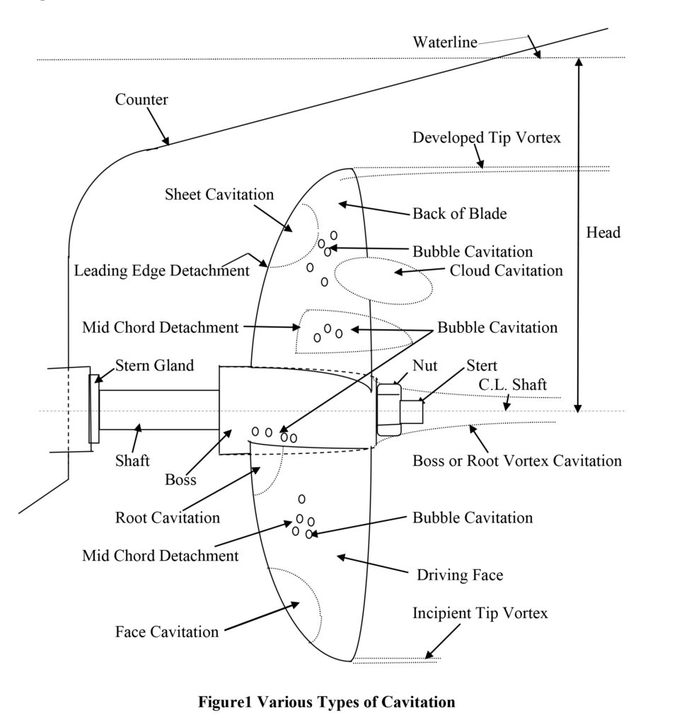
4. Cavitation as an Operating Condition, Not an Anomaly
Cavitation is not a defect.
It is a predictable outcome when local pressure falls below vapour pressure.
It occurs because propellers are designed to operate near hydrodynamic limits. Complete avoidance of cavitation would require unacceptable loss of efficiency and excessive propeller size.
What matters is controlled cavitation.
Uncontrolled cavitation leads to:
- material erosion
- surface roughening
- accelerated fatigue
- noise and vibration
Common cavitation forms include:
- sheet cavitation on the suction side
- tip vortex cavitation near blade tips
- bubble cavitation in disturbed inflow
Once erosion begins, surface roughness increases turbulence, which intensifies cavitation further. Damage progression accelerates non-linearly.
5. Damage Patterns and Their Mechanical Consequences
Propeller damage rarely presents as immediate loss of thrust. It presents as imbalance.
Typical damage patterns include:
- leading-edge erosion from cavitation or suspended solids
- blade tip thinning
- local pitting at collapse zones
- bending from debris or grounding
Even minor geometric changes alter thrust distribution across the disc. This introduces asymmetric loading that manifests as:
- shaft vibration
- bearing temperature rise
- seal wear
- coupling distress
The propeller may still “work”. The propulsion plant is quietly being consumed.
6. Pitch Control, Overload, and Mismatch
In CPP systems, pitch is a load command. Mismanagement of pitch is equivalent to mismanagement of engine load.
Over-pitching at low speed forces engines into:
- high cylinder pressures
- poor combustion
- elevated exhaust temperatures
- turbocharger fouling
Under-pitching wastes power and masks true system capability.
Control failures are often subtle:
- feedback drift
- hydraulic leakage
- actuator hunting
- incorrect manual locking
Engineers often respond by adjusting engine parameters, unaware that the propeller is no longer doing what the control system believes it is.
7. Control Under Real Operating Conditions
Design conditions are rare.
Real operation includes:
- manoeuvring
- slow steaming
- heavy weather
- variable displacement
- fouled hull states
These conditions alter inflow velocity, blade loading, and cavitation behaviour. The most dangerous situations occur during transient changes — rapid pitch movements, crash stops, or heavy-sea RPM adjustments.
Automation reacts to setpoints.
Propellers react to physics.
8. Failure Development and Progression
Propeller-related failures develop slowly:
- erosion reduces margin
- imbalance increases vibration
- vibration accelerates wear
- wear propagates upstream
By the time alarms activate, the system is already operating without reserve.
Sudden failure is rare. Unrecognised deterioration is common.
9. Human Oversight and Engineering Judgement
No sensor measures cavitation directly.
No alarm announces propeller mismatch.
Engineers diagnose propeller condition indirectly through:
- trend deviation
- vibration character
- load anomalies
- unexplained thermal behaviour
A propulsion plant operating at “normal” temperature with rising vibration is not healthy. It is communicating.
Judgement, not instrumentation, prevents escalation.
Relationship to Adjacent Systems and Cascading Effects
Propeller behaviour directly influences:
- shaft alignment stability
- bearing life
- stern tube seal integrity
- gearbox loading
- steering response
- hull vibration and noise
Without understanding propeller hydrodynamics, fault-finding in propulsion systems becomes guesswork.
