Thermal Interfaces, Energy Transfer, and System Boundary Control
System Group: Cooling & Heat Transfer
Primary Role: Controlled transfer of thermal energy between isolated media
Interfaces: Seawater Cooling · HT/LT Freshwater · Lubrication · Fuel · HVAC · Refrigeration · Waste Heat Recovery
Operational Criticality: Continuous
Failure Consequence: Loss of thermal control → cross-contamination → cascading system failures → machinery damage or blackout
Heat exchangers are not accessories.
They are the physical boundaries that allow marine systems to coexist without destroying each other.
Contents
- System Purpose and Design Intent
- Boundaries, Interfaces, and Separation Philosophy
- Fundamentals of Heat Transfer in Marine Machinery
- System Architecture and Placement Philosophy
4.1 Heat Exchangers as System Interfaces
4.2 Media Hierarchy and Pressure Relationships
4.3 Single-Point Failure Concentration - Major Machinery and Heat Exchanger Types
5.1 Plate Heat Exchangers
5.2 Shell-and-Tube Heat Exchangers
5.3 Central Coolers and Multi-Service Units
5.4 Condensers and Phase-Change Exchangers
5.5 Heaters vs Coolers — Structural Similarities
5.6 Gaskets, Plates, Tubes, and Materials - Control Under Real Operating Conditions
- Fouling, Corrosion, and Degradation Reality
- Failure Development and Damage Progression
- Human Oversight, Inspection, and Engineering Judgement
- Relationship to Adjacent Systems and Cascading Effects
1. System Purpose and Design Intent
Heat exchangers exist to perform one task only:
Allow energy to pass while absolutely preventing matter from crossing.
In marine engineering, this is a hostile requirement.
The fluids involved differ radically in:
- chemistry
- pressure
- temperature
- cleanliness
- corrosion potential
Yet they must interact continuously.
Every heat exchanger on board enforces an artificial truce between:
- seawater and freshwater
- oil and water
- fuel and water
- refrigerant and seawater
- exhaust gas and boiler water
This truce is temporary by nature.
The design intent is not permanence — it is controlled degradation, slow enough to be managed within maintenance cycles.
2. Boundaries, Interfaces, and Separation Philosophy
Heat exchangers are deliberate weak points.
Designers concentrate risk into exchangers so the rest of the system can survive.
If seawater must attack something, it attacks:
- exchanger tubes
- exchanger plates
- gaskets
- sacrificial zones
Not engines.
Not bearings.
Not injectors.
This philosophy explains why:
- exchangers are consumable
- redundancy is common
- bypass capability is critical
- isolation valves are mandatory
Any attempt to treat exchangers as “permanent equipment” leads to silent system poisoning.
3. Fundamentals of Heat Transfer in Marine Machinery
Marine heat exchangers operate under:
- high fouling potential
- fluctuating flow
- aggressive corrosion
- continuous vibration
Heat transfer efficiency depends on:
- surface area
- temperature differential
- flow velocity
- boundary layer behaviour
As fouling builds:
- temperature control may remain acceptable
- margin disappears
- pressure drop increases
- failure becomes brittle rather than gradual
Heat exchangers usually fail after they stop being efficient, not when they stop working.

4. System Architecture and Placement Philosophy
4.1 Heat Exchangers as System Interfaces
Every major marine system is connected to another system only through a heat exchanger.
They are the diplomatic checkpoints of the engine room.
Remove the exchanger, and systems cannot interact without damage.
4.2 Media Hierarchy and Pressure Relationships
Correct pressure hierarchy is non-negotiable.
Freshwater pressure must exceed seawater pressure.
Oil pressure must exceed cooling water pressure.
Fuel pressure must exceed service water pressure.
If pressure hierarchy is reversed:
- contamination becomes inevitable
- damage propagates rapidly
- alarms arrive too late
This hierarchy is enforced mechanically, not by procedures.
4.3 Single-Point Failure Concentration
Heat exchangers are single-point failure concentrators by design.
This is intentional:
- one exchanger fails
- one system degrades
- the rest survive
Distributed failure would be catastrophic.
5. Major Machinery and Heat Exchanger Types
5.1 Plate Heat Exchangers
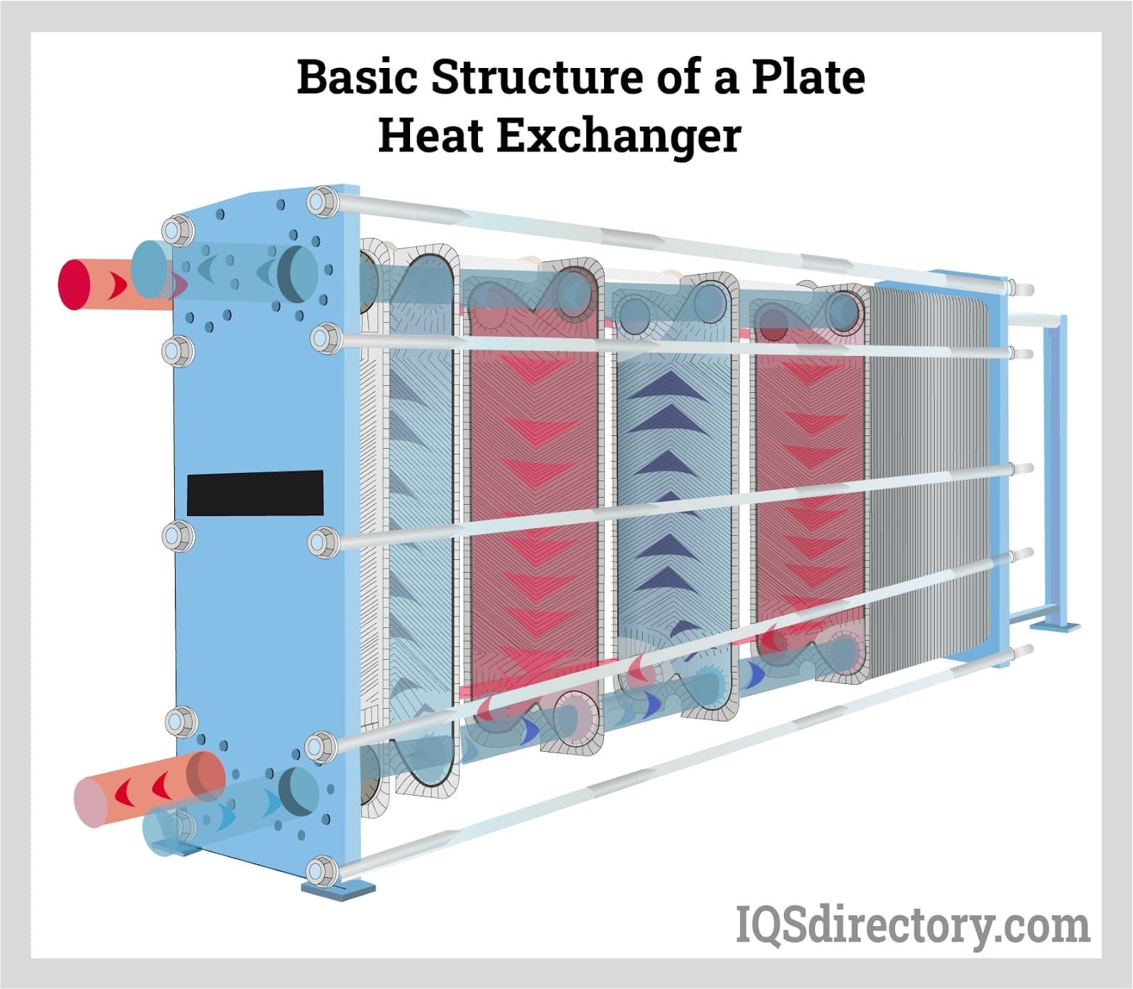
Plate heat exchangers dominate modern ships due to:
- high efficiency
- compact size
- ease of expansion
Their weaknesses are:
- gasket degradation
- plate distortion
- internal bypassing
- sensitivity to fouling
They fail subtly — often continuing to “cool” while contaminating systems internally.
5.2 Shell-and-Tube Heat Exchangers

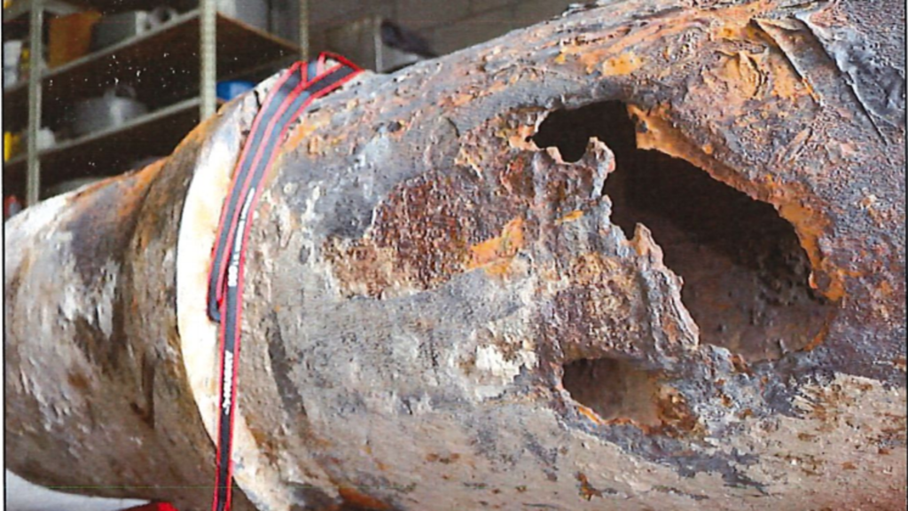
Shell-and-tube exchangers are robust and forgiving.
Their weaknesses include:
- tube thinning
- crevice corrosion
- erosion at inlet zones
- difficult inspection of early failures
They fail slowly, then suddenly.
5.3 Central Coolers and Multi-Service Units
Central coolers combine multiple duties:
- HT cooling
- LT cooling
- auxiliary cooling
They reduce seawater piping but concentrate risk.
Failure here affects the entire plant simultaneously.
5.4 Condensers and Phase-Change Exchangers
Condensers operate at the most unforgiving interface:
- vacuum on one side
- seawater on the other
Air ingress, fouling, or tube failure destroys efficiency immediately.
Vacuum loss is often the first symptom, not leakage.
5.5 Heaters vs Coolers — Structural Similarities
Heaters and coolers differ in purpose, not structure.
Both are:
- pressure boundaries
- contamination barriers
- heat exchangers
Their failure consequences are identical.
5.6 Gaskets, Plates, Tubes, and Materials
Materials are chosen to fail predictably, not to last forever.
Stainless steel resists corrosion but suffers chloride attack.
Titanium resists seawater but is expensive and brittle under vibration.
Rubber gaskets age, harden, and fail invisibly.
Material selection defines failure mode more than service conditions.
6. Control Under Real Operating Conditions
Design conditions assume:
- clean surfaces
- steady flow
- constant temperature
Real ships operate with:
- fouled exchangers
- fluctuating demand
- unstable seawater temperature
Control systems compensate until margin disappears.
When control authority is lost, failure accelerates rapidly.
7. Fouling, Corrosion, and Degradation Reality
Fouling is not uniform.
It begins:
- at inlets
- at low-velocity zones
- where temperature gradients are steepest
Chemical treatment slows corrosion but does not stop it.
Once fouling becomes insulating, metal temperatures rise locally, accelerating attack from the inside.
8. Failure Development and Damage Progression
Heat exchanger failure is rarely dramatic.
Typical progression:
- Fouling reduces efficiency
- Control valves move further open
- Pressure drop increases
- Temperature margin disappears
- Plate or tube breach occurs
- Contamination spreads system-wide
By the time alarms activate, damage has already propagated.
9. Human Oversight, Inspection, and Engineering Judgement
Automation reports temperatures and pressures.
It does not report:
- loss of margin
- internal bypassing
- early contamination
Only engineers notice:
- increasing valve travel
- more frequent cleaning
- unexplained chemistry drift
- rising pump current
Inspection discipline determines survival, not alarms.
10. Relationship to Adjacent Systems and Cascading Effects
Heat exchanger failure destabilises:
- HT/LT freshwater systems
- oil cooling
- fuel conditioning
- refrigeration
- waste heat recovery
Because exchangers sit at system boundaries, their failure is never isolated.